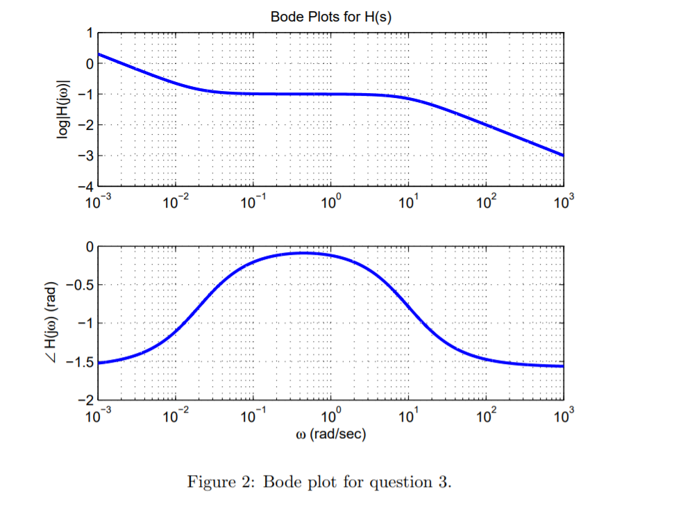

We used the values to draw the Bode plot on the logarithmic paper (2). We used breadboard to construct the circuit and set the function generator on 1KHz, sine wave at 5VP, and then measured the output voltage and recorded the readings. Secondly, with High Pass Filter circuit we looked for the required value of the inductor which was 20mH to get a critical frequency of 5KHz with a resistor value of 620Ω.


We used Bode Plot instrument in Multisim to draw the Bode plot curve and comparing it with the Bode plot on the logarithmic paper (1). Then we used the values in Table.1 to draw the Bode plot on the logarithmic paper (1). We change the input signal frequency and measure the output voltage recording the readings at Table.1. Then we used breadboard to construct the circuit setting the function generator on 500Hz, sine wave at 5VP, then measuring the output voltage with the oscilloscope. We first started looking for the suitable resistor value and we used 4.7KΩ to get critical frequency of 3.4KHz with capacitor 10nF. First, we started with the Low Pass Filter circuit on multism and then applied it on breadboard. The main objective of this project experiment was to design and implement passive filters (LPF, HPF, Series BPF & Series BSF) circuits.


 0 kommentar(er)
